
I thought it would be cool to build a laser switch that triggered my camera’s shutter release anytime something went through the laser. I got the idea from Glacial Wanderer and decided to give it a try.
First, I procured a cheap laser, any laser will do but I took one from a simple laser-level found at The Home Depot. Since I had two of them, I tore one apart and swiped the laser element out of it.
Second, I had to program the Arduino to sense a voltage drop from the Photocell (when something went in between the laser and photocell) and turn off the laser so it doesn’t get in the picture. See schematic below.
And finally, send power to transistor-type switch which I had already built to trigger the camera.

The swiped laser was modified to fit inside a plastic tube. Drilling a hole in a piece of wood and mounting a plastic tube on it would do the trick. I painted it black to limit the light hitting the photocell.

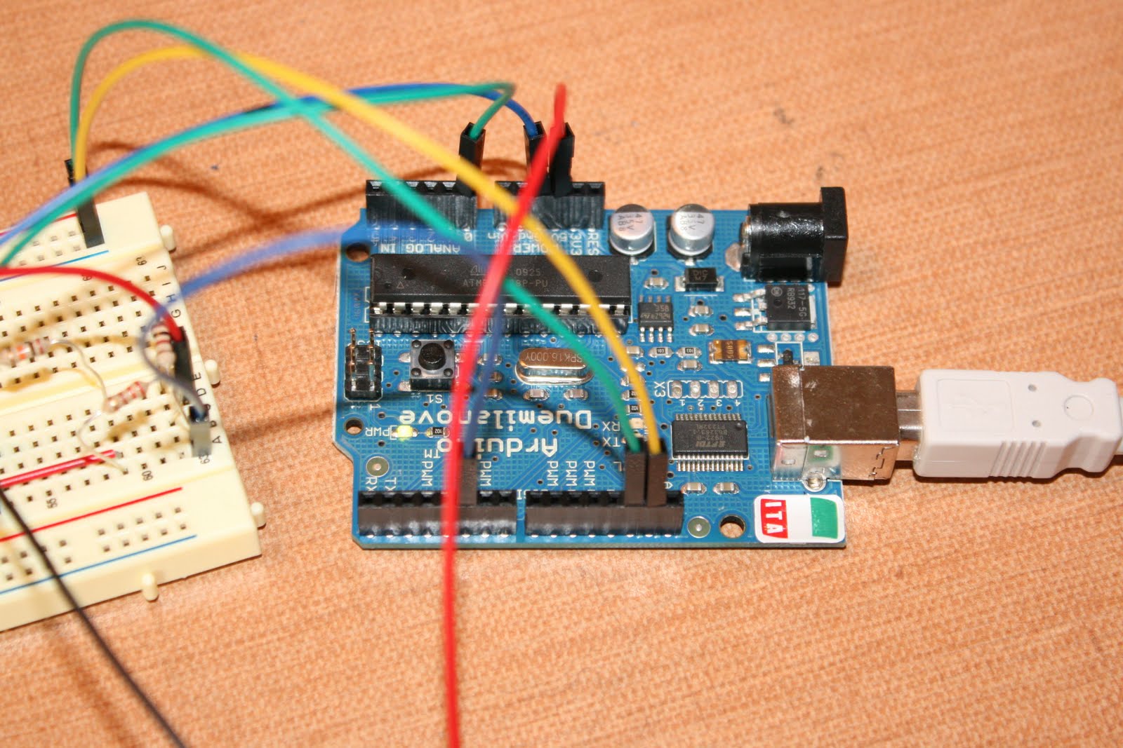
Here is a picture of the Arduino connected to the breadboard.
A closeup of the electronic switch.

The way it works is, the laser is “turned on” as long as the beam is hitting the photocell. As expected, the photocell incurs more voltage as the laser beam is hitting it. It is connected to Analog pin 0 on the Arduino “listening” for a voltage drop. As soon as the voltage drops below the threshold, the code tells pin 5 to “turn off” the laser and send power to in 13 (which is attached to the switch mechanism. The laser begins to pulsate (which is how the code was designed) and pin 13 has enough voltage allow the transistor to light up the LED. I’ve attached the camera jack above the collector of the transistor and to the negative side of the diode so that when enough voltage flows through it “shorts” out the camera switch to take a picture.
The camera switch uses a standard 2.5 mm jack. You could could buy a switch for about $30, but after doing some research, I discovered the switch does nothing more than “short” itself out. See below.


Knowing this, I took a phone headset and cut the wires. Putting the two wires together creates a short-circuit and releases the shutter. It’s one of the simplest ways to create a shutter trigger for about $3.
Here is the code to upload to the microcontroller:
// ORIGINAL DESIGN by Maurice Ribble
// 4-12-2008
//Modified by Josiah Leverich
// The threshhold values for the different triggers.
// These may need to be changed depending on evironment and sensors being used.
// Using PRINT_MESSAGES can help determine the correct value for these.
#define LASER_THRESHHOLD 500
#define CAMERA_FLASH_PIN 13
#define LASER_PIN 5
// The analog pins being used
#define LASER_TRIGGER_ANALOG_PIN 0
void setup()
{
pinMode(CAMERA_FLASH_PIN, OUTPUT);
digitalWrite(CAMERA_FLASH_PIN, LOW);
pinMode(LASER_PIN, OUTPUT);
digitalWrite(LASER_PIN, LOW);
digitalWrite(LASER_PIN, HIGH); // Turn on the Laser
}
void loop()
{
int soundVal;
int laserVal;
laserVal = analogRead(LASER_TRIGGER_ANALOG_PIN);
if (laserVal <= LASER_THRESHHOLD)
{
digitalWrite(CAMERA_FLASH_PIN, LOW);
delay(10);
digitalWrite(CAMERA_FLASH_PIN, HIGH);
delay(100);
digitalWrite(CAMERA_FLASH_PIN, LOW);
digitalWrite(LASER_PIN, HIGH); // Turn laser back on after picture
}
}
No comments:
Post a Comment